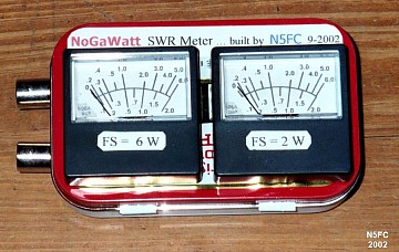
What you'll end up with is an inline wattmeter which shows both forward and reflected power simultaneously, with reasonable accuracy from less than 1/2 watt to 6 watts (full scale). You supply the labor, two RF connectors, and an enclosure of your own design.
Construction
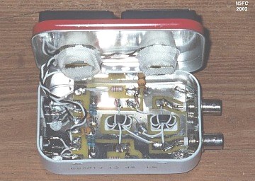
I opted to install mine in an Altoids tin (hey, what else?). So packaged, it makes an exceptionally compact "SWR" meter for portable QRP ops. Since the backside of the meters extend into the same cavity as the rest of the RF components, some effort went into minimizing the profile of the PCB assembly, and locating the meters so that they wouldn't interfere. Here's an inside view of what I did:
Cutting the large holes for the meters was the toughest part of the job. I took the
crudest approach possible. After removing the lid from the Altoids tin, I used a step
drill to make 1/2-inch holes (the largest I can make with my unibit). Then, I used a knife
to cut numerous sun-rays in each hole, so I could fold them back, making a larger hole.
The folded-back flanges act to capture the meters in place (like a giant push-on nut).
These flanges are razor sharp, so to protect against cuts and assure the flanges didn't
cause electrical shorts, we taped the flanges and the meter backs thoroughly with glass
tape (friction tape would have been just as good, but vinyl electrical tape probably
wouldn't hold up).
The PCB (printed circuit board) was mounted to the bottom of the Altoids tin with double-foam tape. All parts were mounted topside on the PCB, surface-mount style (even if they weren't surface-mount parts. Thus, when closed, the meter backsides dodge the toroids, and there is no electrical or mechanical interference with any of the internal parts (and not a lot of clearance, either).
I chose to use BNC connectors for I/O. I placed them such that they could be soldered directly to their pads on the PCB.
Modifications
You can pretty much see what I did in the picture above, but here's a list of mods and substitutions I made. Most were made for mechanical reasons (i.e., clearance), and not for functionality.
1. Where shown, solder a braid from the "ground plane" on the PCB to the inner wall of the Altoids tin, right next to the connectors. Obviously, I chose to use BNC connectors.
2. I wound the toroids with teflon wire, because it's a better RF insulator. (probably, doesn't make any difference).
3. I substituted molded chokes for the chokes provided (lower profile).
4. I mounted the two pots using double-side foam tape, using a hole in the side of the Altoids tin to afford screwdriver access for calibration.
I also opted to calibrate the "reflected" power meter for 0-2 watts (rather than 0-6), so that it would have a little more visual deflection at low reflected powers. Also, since this is a true bi-directional bridge circuit, I can swap the input and output cables, and measure my forward power a little more accurately using the 0-2 watt meter when I'm running QRPp.
Conclusions
This meter works great! After calibration according to the procedure outlined in the manual (which involves measuring the voltage across a dummy load using an RF probe), the wattmeter measured nearly identically to my MFJ-970 tuner's built-in 0-6 watt meter, from 80 through 10 meters into a matched load. I was a little worried that having the meters so close to the toroids would cause a problem, especially at the higher frequencies, but it seems to work marvelously!
Thanks, NoGa, for a fantastic kit and a superb bargain!
73, monty N5FC