The NOGA PGR-80 (Pretty Good Receiver)

By Mike Boatright, KO4WX

How do I...?

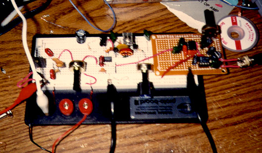
The December, 1998, meeting of the North Georgia QRP Club was dedicated to construction of a 1 watt 80 meter transmitter. I was only able to stay at the meeting for a short time, so I built mine at home, using "butt ugly" construction.

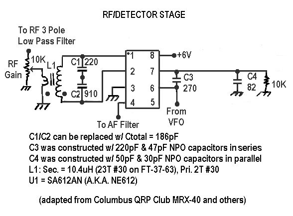
Silly man that I am, I decided that "wouldn't it be nice if I had a simple receiver to go with this transmitter?" Discovering that Tech America stocked the SA612AN, which is the same device used in the Columbus QRP Club's MRX-40 (they used an NE612). The MRX-40 is a nifty little XTAL controlled receiver that was created as a companion to the Micronaut transmitter, featured by Dave Ingram, K4TWJ in a series of articles in 1997 in CQ Magazine.

Just to show how limited my design skills were, I made the following post, one Saturday night around 9:00PM (EST) to the QRP-L list:

    As a nice companion to the NOGA 80 transmitter, I'm looking to build an NE612 based, SIMPLE receiver, following K8IDN's MRX-40 design. I'm a bit baffled by the receiver input circuit and was wondering if anyone could help me out. In a nutshell, the 40m receiver input is like this:
ant +--------+--------+ NE612 \|/ | | | IC | = C1 | +- Pin 1 / R1 47 | 91pF )L1 \<-----------^^^-----+ (5.6uH +- Pin 2 / R4 10Kohm | ) | | variable = C2 | | | | 470pF | | | +--------+--------+ | | | = C3 | | 0.1uF --- --- /// ///
  1. What would be the appropriate values for C1, C2 and L1 for 80meters (3686KHz)?
  2. How does this input circuit work and what are the appropriate formulas for calculating C1, C2 and L3?
  3. With regard to 2, I THINK this is a "balanced input", but am not 100% sure. I think it's balanced, since the 470pF capacitor is not grounded. Also the ARRL Handbook says that the NE602 (similar to the NE612, but not the same) has an AC impedance of 1500 ohms in parallel to 3pF of capacitance. Does this factor into the equations for Q2?
  4. I'm sure the point of this input circuit is to be resonant around 7040KHz. How, exactly, is the circuit resonant? It's the split capacitors that confuses me.
Completed NOGA 80 (before PGR project)

Completed NOGA-80 (before adding T/R switching).

Inside view of NOGA-80.

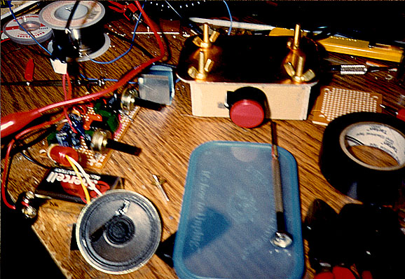
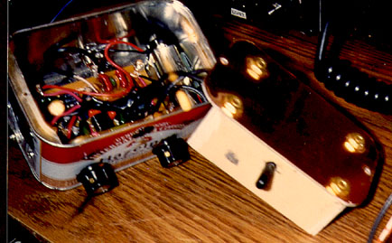
Inside view of NOGA-80 (first attempt at T/R switch is at lower center of PCB).


QRPers Never Sleep!

By 9:00AM (EST), Sunday morning, I had 4 responses in my e-mail!

To net out the responses, I learned that the way to scale a resonant circuit from one frequency to the next is to calculate the values of XL (inductive reactance) and and XC (capacitive reactance) in the resonant circuit. Where:

XL = 2 * PI * F * L and XC = 1 / 2 * PI * F * C In the MRX-40 circuit, you have to use the total capacitance (Ctot) of C1 and C2, which can be calculated by: Cot = C1 * C2 / (C1 + C2) In case you were wondering, C1 and C2 in the MRX-40 were chosen such that XC2 = approx. 50ohms, at 7MHz, which matches directly to the 50ohm antenna.

Glen Leinweber, VE3DNL was the first to write, and really helped me understand this. With the above equations in mind, Glen said,

To convert to 80M: Let's scale it exactly. First choose an inductor with exactly the same reactance at 80M as this one does at 40M. Reactance of 5.6uH at 7Mhz is 2*PI*F*L = 246.3 ohms. At 3.6MHz, 246.3 ohms works back to an inductance of 10.88uH You can do the same with C1 and C2 as well: C1's reactance at 7MHz: 249.85 ohms C1's capacitance at 3.5 MHz: 177pf C2's reactance at 7MHz: 48.37 ohms C2's capacitance at 3.6MHz: 913.99pf And notice that C2/C1 ratio is still 5.16, same as before (at 7MHz)

Let's Get That Sucker Tuned Up!

After a couple of days fooling around with scaling the input tuned circuit, I made my first trip (of many!) across town to Tech America. Cool! The SA612AN goes for $2.52 (less than the SA602AN), so I got a bunch of them, plus some toroids, perfboards, trimmer capacitors, etc.

For my first stab at the "MRX-80" on the breadboard, I chose a 220pF capacitor for C1 and a 910pF for C2. L1 became 10.4uH, which was worked out using the ARRL handbook formulas for ferrite toroids (I chose ferrite for its high permeability and given that heating/saturation should not be a problem--I sound smart, but these recommendations came out of W1FB's QRP Notebook). L1 is 23 turns of #30 enamel wire on an FT-37-63.

The first tuned circuit for the NE612 Local Oscillator, used a 3.686MHz crystal, 39uH choke (from the junk box), and a 1N4001 diode (forward biased with +6V though a 10K variable resistor and a 100K resistor) all in series from pin 6 on the NE612 to ground

I'm not showing the diagram for this circuit, because basically, I was not at all pleased with how well the crystal would warp. I tried several incantations and instantiations of the VXO, without results that in any way pleased me. It may be the Q of the circuit. I'm not sure. All I know was that the best I could get the crystal to warp was about 500Hz--not very good. I finally decided to use a BFO--more about this later.

Anyway, I put the scaled MRX-40 circuit (with the VXO mod) together on the breadboard, with both the NE612 and LM386 (AF amplifier). I fired the whole thing up, and got a wonderful howling sound. Lesson learned: Always use the shortest leads possible, and bypass capacitors, especially on the power supply and output leads. I configured the LM386 with a 10uF capacitor across pins 1 and 8, which yields a gain of 200. This is sufficient to lift the signal coming out of the NE612 to a comfortable listening level, but with that much gain in a single stage, it's really easy to get feedback and self-oscillation.


RCI BCI

Once the sun was down, and the howling dispensed with, it was time to try out the receiver with a real antenna attached. I hooked it up (using clip wires) to my HF6V (80-10). My, how nice Radio Canada International sounded on 7.3MHz (in my 80M receiver!).

I remembered that Sam Billingsley, AE4GX (who also helped me with the scaling exercise), had had severe problems with 39 meter BCI in his PIXIE kit, which he fixed with a specially designed filter. So, I grabbed my W1FB QRP Notebook and wired up a quick 3-pole low-pass RF filter for 80 meters (page 103), to see if that would help. Knocked the RCI BCI down quite a bit, but still a S9 or better signal.

At this point, however, I started to hear 80 meter CW signals! Wow, I was impressed! This theory stuff really does work!

So the RF 3-Pole Low-Pass Filter shown here became a permanent part of my new receiver design.

RF 3 Pole Low-Pass Filter

Varactor Tuned BFO

Two Birds With One VFO?

Another trip or two later to Tech America, I decided to tackle the VXO problem. In one of my experiments with trying to warp the 3.686MHz crystal, I had tried using an MV104 varactor (variable capacitance, or varicap) diode (actually the MV104 has 2 varactor diodes in it). Although I wasn't pleased with how it had performed in the VXO, I decided to try it as part of the tuned circuit in a VFO.

Again, borrowing from W1FB (p. 123), I breadboarded up a 3.6MHz VFO. Darned if the thing didn't fire up first time. With just a little tweaking, I was able to get the BFO to swing approximately 129KHz, Very nice indeed! The thing was pretty rock stable, as well--woo-wooing, of course, when I moved my hand near the oscillator--but otherwise, staying nearly dead on, even after extended periods of continuous operation.

One other thing that Sam, AE4GX, had shared with me was that making the input circuit balanced, instead of unbalanced (as it is in the MRX-40) might also help with SWL BC band rejection. I took the input signal from R1 in the original MRX-40 and connected it to the "top" end of a two-turn loop around L1 (connected on the same end of L1 as Pin 1 on the NE612). I connected the "bottom" end (the pin 2 side) to ground, and removed C3 from the circuit.

One little VFO solved two different problems!


RF/Detector Stage

At this point, I could have removed C1 and C2 and replaced them with a single 186pF capacitor, but why bother? If I really wanted a perfect circuit, a 160pF in parallel to a 25pF or 35pF trimmer would have been better, but I was pleased with what I had.

While in the process of building the BFO, I remembered something I had read in W1FB pointing out that one of the shortcomings of the integrated mixer/LO devices (NE602, NE612, etc.). As a result of the LO being on the chip, it is difficult, if not impossible to prevent second and third order harmonics from being generated in the LO. Wow, 3.686 * 2 = 7.372, almost dead on Radio Canada International. Whatever 39 meter signals were getting through the filter, were being beat down quite nicely by what I am sure was a significant 7.3MHz harmonic, hence the significant BCI still coming through after all the work on the front end.

By the way, I would suspect that this same situation exists in the PIXIE due to the close integration of the oscillator and the product detector/mixer.

RF/Detector Stage

Hey, this is a pretty good receiver!

Hey, this is a pretty good receiver!

At this point, I had a functioning receiver, and the 39 meter BCI from Radio Canada International was nearly all gone. I was lazily enjoying listening to the music of the Novice band CW (about all I'm really any good at copying!). At this point, I began moving the entire circuit off the breadboard and using a more permanent perfboard construction method (my preferred technique).

In this photo, I've moved both audio stages off of the breadboard. The variable resistor on the perfboard is the AF Gain control. The two chips are the LM386 and a TL082 used as a low-pass filter, as described in the next section.

For what it's worth, the purchase of a breadboard similar to this one is a must for anyone serious about construction. I can no longer imagine life without it. Also, heavy investment in solder wick is highly recommended!


The Audio Stages

I've heard it said, "Oh no, not another LM386 receiver!" Well, it sure does carry it's weight, especially for a low-profile, low-parts count receiver. This sucker is pretty rock solid. I chose the LM386-3, which operates on a +9V Vs. In the final configuration of the receiver, I added a 8.2V Zener diode in front of this, and the device worked fine with no apparent degrading of the signal level (using the very high-tech test tool "MYEAR").

It is very critical that you use a good regulated supply and good bypassing. Without the 1uF electrolytic capacitor the circuit would oscillate very badly. The bypass from pin 7 to ground is specified in the data sheet, but the circuit worked just fine without it. Your results may vary. I decided to put it in. Also, the 10 ohm resistor and the .1uF capacitor set the output load/impedance and seem to help stabilize the circuit as well. The 10uF capacitor between pins 1 and 8 sets the gain at 200. If you are following this stage with another level of audio amplification, remove this capacitor (to set the gain at 20) or put a small resistor (1K ohm or so) in series to set the gain between 20 and 200. The polarity of the electrolytic capacitor does not seem to matter. I put the "+" side on pin 1, but I know it worked either way.

Audio Amplifier
AF Low-Pass Filter

To improve receive performance, I breadboarded up a 350Hz bandpass filter, but found it extremely difficult to tune the radio. When I use my QRP+, I always set the bandpass very wide, when I'm tuning around the bands, and only use the tight 100Hz filter, when I want to get dead on a signal. I realized that to achieve this, I'd have to add a bypass switch (another part, more complexity), plus, what I really needed was a wide filter and a narrow filter (I had only build a 2-pole filter, with about 350Hz bandpass).

In Solid State Design for the Radio Amateur, Wes Hayward, W7ZOI, and Doug Demaw, W1FB (now SK), recommend use of low-pass filters in simple QRP gear. On page 223, they present a QRP rig with such a filter. This filter is shown above. It has a 1KHz cutoff, and really works well. It cuts off the noise significantly. While adjacent signals can still be heard, it makes a dramatic improvement in the signal quality, and is worth the tradeoff.

If I wanted a VGR (Very Good Receiver), I'd incorporate both types of filters. But the low-pass filter works very nicely in this radio.

AF Low-Pass Filter Construction Detail

PGR-80 Final Construction

Putting it All Together

The complete PGR-80 is shown in the photo on the left. The BFO has been placed in a box constructed of single-sided PC-board material. The DC power is supplied with using a piece of RG-174, with the shield soldered to the copper on the inside of the box, which is also connected to ground on the BFO perfboard. The BFO signal is supplied to the NE612 via RG-174 in a similar manner. An 78L06 on the BFO board regulates the supply, so either 9V or 12V supply is OK.

To the left of the photo are the audio stages, the RF/Detector Stage, and the RF 3-Pole Low-Pass Filter. The variable resistor on the left is the AF Gain, and the one on the right is the RF Gain. The NE612 sits just behind the RF Gain.

The AF stages provide enough audio that the small 500mW speaker works pretty well. For serious operation, headphones are recommended. The jack switches the speaker off when the headphones are inserted.


Finishing Touches

I like rigs in interesting containers. I've had these coffee tins for quite some time and decided that this was the project for them.

The audio/RF board fits quite nicely in the bottom of the the tin. The top of the BFO box, which is made out of dual-sided PC board, becomes the top of the rig. This inserts over the top of the perfboard and screws in snuggly. There is room next to the perfboard for the 9V battery, and a small 1/8" jack is used to allow for an external 12V source.

The speaker fits in neatly to the side just over the headphone jack, and is held in place with small bolts (the nuts press against the backside of the speaker).

PGR-80 Final Assembly in Coffee Tin

The NOGA Twins

The NOGA Twins

And here are the NOGA Twins, the NOGA-80 transmitter (also called by some, the "Georgia Cracker") and the PGR-80 (Pretty Good Receiver). My version of the NOGA-80 has two crystals, 3.686MHz and 3.579MHz, switch, and the VXO tunes about 800-1000Hz around the center frequency.

I experimented with a diode Transmit/Receive switch, but only managed to cause very severe chirp in the transmitter (I suspect I was seriously loading the final). So I settled on a manual T/R switch for this version of the project. Always room for improvement!


The Pretty Good Receiver (Summary)

Direct Conversion Receiver Block Diagram

In summary, this project did not yield any new innovations in receiver design. Every technique that I used was borrowed, and I relied heavily on the advice of my Elmers. But it was a whole lot of fun, and I got a whole lot more than I had bargained for when I put out my first question on the "L".

I learned that every design project is one of balancing conflicting objectives, such as price vs. performance, bandwidth vs. selectivity, etc. Everything is a compromise, but I found that a pretty good receiver can be built with a very low parts count (about 50).

One of the coolest aspects of this project is that every part used can be purchased at Tech America. When I get a hankering to build something, I hate waiting for parts to arrive (I'm seriously into instant gratification). The parts list will be forthcoming.

Thanks again to all my Elmers, particularly, Sam, AE4GX, and Wes, W7ZOI. 72!